Understanding current and resistance dynamics can feel like a daunting task, especially for those who are new to the field of electrical engineering. However, having a solid grasp of these fundamental principles is crucial for both beginners and seasoned professionals looking to refine their skills. Whether you’re trying to design a new electronic gadget, troubleshoot an existing system, or simply want to comprehend how your household appliances work, this guide aims to demystify these concepts. Let’s dive into a step-by-step approach to understand the intricacies of current and resistance dynamics.
This guide is crafted to provide you with actionable insights, real-world examples, and practical solutions to any challenges you may face. Our aim is to address your specific pain points and to deliver clear, concise, and practical information to help you succeed. By the end of this guide, you’ll not only understand these concepts better but also be able to apply this knowledge effectively in your projects and everyday life.
Quick Reference
Quick Reference
- Immediate action item with clear benefit: Start with Ohm’s Law (V=IR) to assess the relationship between voltage, current, and resistance.
- Essential tip with step-by-step guidance: Measure current using an ammeter in series with your circuit to accurately gauge how much current is flowing.
- Common mistake to avoid with solution: Misplacing components when creating a circuit. Ensure that resistors and other components are placed correctly according to the circuit diagram.
Understanding Current and Resistance Dynamics: The Basics
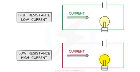
Current is the flow of electric charge through a conductor, typically measured in amperes (A). Resistance, on the other hand, is a measure of how much a material opposes the flow of current, measured in ohms (Ω). To fully grasp these dynamics, it’s important to delve into the foundational laws and principles that govern them. Below, we’ll explore these fundamentals in detail, breaking down complex concepts into simple, understandable segments.
Ohm’s Law
Ohm’s Law is a cornerstone of electrical engineering, providing a simple relationship between voltage (V), current (I), and resistance ®. It is expressed as:
V = IR
This formula states that the voltage across a resistor is equal to the current flowing through it, multiplied by its resistance. To put this into a practical context, imagine you have a voltage source of 10V and you want to find the current through a resistor of 5Ω. Applying Ohm’s Law:
I = V / R = 10V / 5Ω = 2A
This means the current through the resistor is 2 amperes. Understanding this basic formula will help you solve more complex problems.
The Role of Components
In electrical circuits, components such as resistors, capacitors, and inductors play critical roles. Each component affects current and resistance differently:
- Resistors: Directly oppose the flow of current and can be used to divide voltages across multiple points in a circuit.
- Capacitors: Store and release electrical energy, behaving differently at different frequencies.
- Inductors: Oppose changes in current and can store energy in a magnetic field.
Practical Application: Designing a Simple Circuit
Let’s put theory into practice by designing a simple series circuit. Suppose you want to power a small LED light with a 9V battery. The LED has a forward voltage of 2V and requires a current of 20mA. To ensure the LED works properly, you need to calculate the appropriate resistor value:
The total voltage from the battery is 9V, and the LED drops 2V. Thus, the voltage across the resistor will be:
V_resistor = V_battery - V_LED = 9V - 2V = 7V
To limit the current to 20mA (0.02A), we use Ohm’s Law:
R = V / I = 7V / 0.02A = 350Ω
So, you would use a 350Ω resistor to ensure that the LED receives the correct current. By following these steps, you can design circuits that work effectively and safely.
Advanced Techniques for Managing Current and Resistance
Once you’ve mastered the basics, it’s time to delve into more advanced techniques for managing current and resistance. These methods are particularly useful for professional applications where precision and efficiency are paramount.
Using Complex Circuit Configurations
Simple series and parallel circuits form the basis of more complex configurations such as delta and wye networks. Understanding these configurations allows for more sophisticated control over current and resistance:
Delta and Wye Networks
In delta (Δ) and wye (Y or star) configurations, resistors are interconnected in ways that provide more flexibility:
For delta configurations, the relationship between resistances R1, R2, and R3 is:
R1 = (R2 * R3) / (R2 + R3 + R1)
R2 = (R1 * R3) / (R1 + R3 + R2)
R3 = (R1 * R2) / (R1 + R2 + R3)
For wye configurations, the relationship is:
R1 = (R2 + R3) / (R2 * R3)
R2 = (R1 + R3) / (R1 * R3)
R3 = (R1 + R2) / (R1 * R2)
Current Division and Current Sourcing
Current division and current sourcing are advanced methods for calculating current in complex circuits. In current division, the total current is split among parallel branches according to their resistances:
For a branch in a parallel circuit with resistance R, the current I through that branch is given by:
I_branch = I_total * (R_branch / R_total)
Where I_total is the total current entering the parallel combination and R_total is the total resistance of all branches combined. For current sourcing, you can apply similar principles to source current from a voltage source through different resistances.
Practical FAQ
How can I measure current in a circuit without disrupting its operation?
To measure current without disrupting the circuit’s operation, use an ammeter. An ammeter must be connected in series with the part of the circuit where you want to measure current. Ensure the ammeter has the correct range to avoid any damage or inaccurate readings. Always turn off power before making connections to prevent short circuits.
Why do resistors fail in a circuit?
Resistors fail in circuits due to several reasons:
- Overcurrent: When the current exceeds the resistor’s rating, it can cause the resistor to overheat and burn out.
- Thermal stress: Rapid changes in temperature can cause mechanical stress, leading to failure.
- Manufacturing defects: Sometimes, resistors may have manufacturing flaws that lead to premature failure.
To prevent these issues, always choose resistors with appropriate power ratings for your circuit and ensure they are correctly placed in the circuit.
What are some tips for choosing the right resistor for my circuit?
Selecting the right resistor involves considering several factors:
- Resistance value: Ensure it matches the requirements of your circuit.
- Power rating: Choose a resistor with a power rating higher than the maximum power it will dissipate to ensure durability.
- Tolerance