Mastering Rod’s Moment of Inertia: Insights!
Understanding the moment of inertia for a simple rod is fundamental in many physics and engineering disciplines. It’s crucial for analyzing rotational dynamics, mechanical systems, and structural integrity. Here, we dive deep into the nuances of the moment of inertia for a rod, providing practical insights and actionable recommendations to ensure you fully grasp this concept.
Key Insights
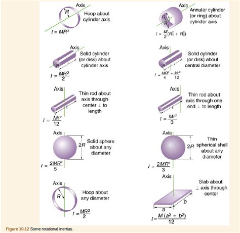
- Primary insight with practical relevance: The moment of inertia for a rod around its center is given by I_{center} = \frac{1}{12} m L^2, where m is the mass and L is the length of the rod. This insight is particularly relevant in designing systems where rotation around a central axis is key.
- Technical consideration with clear application: Understanding the moment of inertia's dependence on the distribution of mass is essential for precise calculations in rotational dynamics and structural analysis.
- Actionable recommendation: Always use the parallel axis theorem when calculating the moment of inertia for different axes that are not through the center of mass to avoid computational errors.
Concept of Moment of Inertia
The moment of inertia, often denoted as (I), is a measure of an object’s resistance to changes in its rotational motion about a particular axis. For a rod, this concept becomes essential in analyzing its rotational behavior. The moment of inertia of a rod about its center is (I_{center} = \frac{1}{12} m L^2). This formula derives from integrating the differential elements of mass (dm) multiplied by the square of their distance from the axis (r^2). The significance of this formula is paramount in designing rotational systems and understanding their stability and dynamic response.Calculation Variations and Practical Application
While the center-axis moment of inertia is a straightforward calculation, variations are needed for practical applications, especially in real-world engineering problems. For instance, calculating the moment of inertia around an end of the rod, we use the parallel axis theorem. This theorem states (I{end} = I{center} + m \left(\frac{L}{2}\right)^2 = \frac{1}{12} m L^2 + \frac{1}{4} m L^2 = \frac{1}{3} m L^2). This adjustment accounts for the shift in the rotational axis, which is a common scenario in engineering contexts where components rotate around fixed points.What is the moment of inertia for a rod rotating about its center?
The moment of inertia for a rod rotating about its center is I_{center} = \frac{1}{12} m L^2.
Why is the parallel axis theorem important?
The parallel axis theorem allows for calculating the moment of inertia around any axis parallel to the center of mass, which is crucial for determining rotational dynamics when the axis of rotation is not through the center.
In conclusion, mastering the concept of a rod’s moment of inertia not only enhances your understanding of rotational dynamics but also equips you with the tools needed for precise and effective engineering design. From theoretical calculations to practical applications, the insights provided here will ensure you approach problems with confidence and accuracy. Always remember, understanding the distribution of mass and how it influences rotational motion is key to advancing in the fields of physics and engineering.